QA Graphics has expanded its 3D symbol library to be compatible with more building automation systems (BASs). The 3D symbol library has been expanded by the company's design team to operate smoothly with most BAS software. A core part of QA Graphics' business is graphic outsourcing, taking mechanical control drawings and creating system graphics for the end user.
As a result, the library was developed to provide the industry with more appealing and realistic graphics than provided with BAS software. The symbol library provides equipment and components to consistently assemble high-end system graphics. Users can spend less time assembling graphics. This 3D symbol library has been implemented into numerous facilities for several control system manufacturers.
With more than 200 static graphics and more than 80 animated graphics, the symbols can be used to create most major mechanical systems. The library is available at two levels: commercial, which provides an extensive variety of graphic options to create almost any system graphic; and Lite Commercial, a condensed symbol set to create system graphics. Symbols include boilers, chillers, dampers, filters, piping, fans, cooling towers, generators, valves, ductwork and coils.
Each library is provided for unlimited use by one physical company location and may be used by additional locations for a one-time licensing fee. Users of the symbol library can continually provide high-end system graphics and represent mechanical control drawings in a schematic, graphical view. The library is also constructed to be branded to the user's business, with a visible watermark of a three-letter acronym displayed on major equipment components to protect the graphics. The watermark can also be used so that it is undetectable by the end user.
Showing posts with label 3D. Show all posts
Showing posts with label 3D. Show all posts
3D Measuring Software Available For Faro Gage
 Faro and Aberlink have signed an agreement under which the Aberlink 3D software is available as an option for the Faro Gage. Aberlink 3D can now be employed with portable measuring arms and was designed around an intuitive user interface that creates an interactive 3D image of the component as it is measured.
The software package represents an intelligent measuring system that is able to automatically recognise and define the various features being measured. Software features developed specifically for Faro measuring arms ensure the on-screen image is always correctly orientated to match the measured part. Other innovations allow the arm to be used to control mouse functionality and the arm buttons to retake points and accept features.
High-speed scanning enables a standard fixed probe to be used to collect a high density of touch points using time- and distance-based point spacing.

XVL Converter Compresses 3D Autodesk Inventor Data
Lattice Technology has released the XVL Converter Plug-In for Autodesk Inventor 2010. The XVL Converter Plug-In for Autodesk Inventor allows 3D data created in Autodesk Inventor 2010 to be compressed to an average 0.5 per cent of its original size without loss of accuracy. As XVL data, the 3D designs can be rapidly mocked up for simulation, design review, process design, kinematics and human interaction on the assembly line.
XVL data is also used to directly and rapidly create print-ready and interactive digital documentation for mBOMs, process and work instructions and technical illustrations. Lattice Technology's applications allow 3D design data from diverse sources and CAD platforms to be integrated into a single assembly model, and because of the compression, can still be easily used and manipulated on low-specification PCs.
The small size of the data means it can be used interactively in locations such as the shop floor and shipping departments, which have typically never benefitted from 3D data before. Automatic updates of mock ups, simulations and technical documentation when the original 3D data is changed is also easy with the Lattice Technology Solutions. This latest converter is available for customers with current maintenance contracts; it is also available for trial.
XVL data is also used to directly and rapidly create print-ready and interactive digital documentation for mBOMs, process and work instructions and technical illustrations. Lattice Technology's applications allow 3D design data from diverse sources and CAD platforms to be integrated into a single assembly model, and because of the compression, can still be easily used and manipulated on low-specification PCs.
The small size of the data means it can be used interactively in locations such as the shop floor and shipping departments, which have typically never benefitted from 3D data before. Automatic updates of mock ups, simulations and technical documentation when the original 3D data is changed is also easy with the Lattice Technology Solutions. This latest converter is available for customers with current maintenance contracts; it is also available for trial.
Build Material Increases 3D Printed Model Demand
The Realization Group is using a combination of Z Corporation's ZP150 build material and the multicolour 3D ZPrinter450 to meet demand for models with richer colours and improved mechanical strength. 'Purer whites are especially important for architects, who traditionally prefer white models early in the design process so they can consider design, massing and space without the distraction of colour,' explains Rafael Tapanes, founder of the multidimensional architectural visualisation firm. 'Although earlier generation bone-white models are acceptable, customers have long been asking for pure white,' he added.
Architecture is a key sector for Realization Group, which helps clients breathe life into abstract concepts. Finely detailed physical massing models are created rapidly and cost effectively using the recently installed ZPrinter450 multicolour twin-head 3D printer. 'Speed is the key,' said Tapanes. 'I can take an order for a model today and deliver it to the customer tomorrow. 'We can accept formats for printing that include STL, VRML, PLY, 3DS and ZPR files.
'I can also make models for one-quarter the cost of stereolithography or laser cutting,' he added. Models as large as 203 x 254 x 203mm can be built at a speed of 23mm per hour, while automation features include: automated set-up and self-monitoring; automated powder loading; automated powder recycling and removal; snap-in binder cartridges and an intuitive control panel. The combined effect is that Realization Group can now offer customers two or three printed models for what used to be the price of one. Demand from architects is escalating.
In contrast to the pure whites sought by architects, developers prefer multicolour models so they can fully grasp the concept behind a proposal and begin selling it while it's still in development. Tapanes said the improved colour saturation in ZP150 build material is giving developers brighter colours across the spectrum. With 604 jets operating from two print heads, the ZPrinter450 maximises the colour potential of ZP150 build material on this printer platform, offering printed resolution of 300 x 450dpi.
Model strength has been noted as another improvement. 'I no longer have to advise clients how to handle their models,' said Tapanes. 'If I cure a ZP150 model with ZBond, it's virtually indestructible and has an ultra-smooth finish,' he added. ZP150 is available through Z Corporation's worldwide reseller network. It is compatible with the ZPrinter450 and ZPrinter650 colour 3D printers.
Architecture is a key sector for Realization Group, which helps clients breathe life into abstract concepts. Finely detailed physical massing models are created rapidly and cost effectively using the recently installed ZPrinter450 multicolour twin-head 3D printer. 'Speed is the key,' said Tapanes. 'I can take an order for a model today and deliver it to the customer tomorrow. 'We can accept formats for printing that include STL, VRML, PLY, 3DS and ZPR files.
'I can also make models for one-quarter the cost of stereolithography or laser cutting,' he added. Models as large as 203 x 254 x 203mm can be built at a speed of 23mm per hour, while automation features include: automated set-up and self-monitoring; automated powder loading; automated powder recycling and removal; snap-in binder cartridges and an intuitive control panel. The combined effect is that Realization Group can now offer customers two or three printed models for what used to be the price of one. Demand from architects is escalating.
In contrast to the pure whites sought by architects, developers prefer multicolour models so they can fully grasp the concept behind a proposal and begin selling it while it's still in development. Tapanes said the improved colour saturation in ZP150 build material is giving developers brighter colours across the spectrum. With 604 jets operating from two print heads, the ZPrinter450 maximises the colour potential of ZP150 build material on this printer platform, offering printed resolution of 300 x 450dpi.
Model strength has been noted as another improvement. 'I no longer have to advise clients how to handle their models,' said Tapanes. 'If I cure a ZP150 model with ZBond, it's virtually indestructible and has an ultra-smooth finish,' he added. ZP150 is available through Z Corporation's worldwide reseller network. It is compatible with the ZPrinter450 and ZPrinter650 colour 3D printers.
Objet Offers Digital Material Pack For 3D Printers
 Objet Geometries has released a digital material pack that allows manufacturers and designers to create suitable parts and models for product-design testing, simulation and validation. The offering is only available on the Connex350 and Connex500 - 3D printers that are capable of simultaneously printing multiple materials with different mechanical and physical properties.
The pack provides 3D printing users with 18 new materials comprised of combinations of Verowhite and Tangoplus or Tangoblack Plus, the latest addition to the Tango range. The materials encompass the full Shore A hardness scale (from 27 to 95), characterising a range of rubber-/elastomer-based products.
With these materials, Connex users can print parts, such as wires and cables, grips and handles, plugs and connections, shock absorbers, function buttons, gaskets and seals, among other rubber applications. The rigid materials simulate the strength and toughness of products made of such standard plastics as PP, LDPE, HDPE, PVC and PS. Up to 11 different rigid and flexible materials can be combined in a single part in one build.
Stallion 3D Enables 3D CFD Analysis
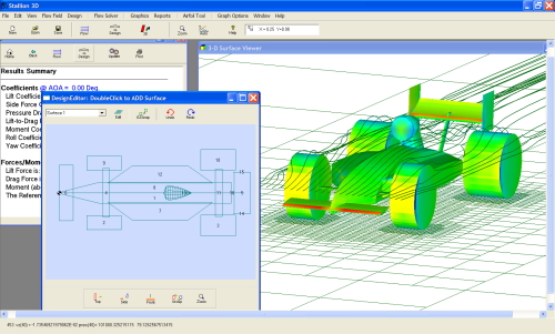 Hanley Innovations has announced the availability of Stallion 3D, an all-in-one 3D compressible flow analysis software package for Windows XP/Vista PCs. Stallion 3D allows users to enter single or multiple CAD drawings (saved in the .stl file format) into the program for a 3D computational fluid dynamics (CFD) analysis. In addition, components such as wings, cylindrical shapes and closed bodies can be added to the analysis using the built-in geometry engine.
Users can position and rotate any of the components to match a desired test setup. The built-in pre-processor automatically detects the immersed boundaries and generates a Cartesian grid for the entire flow field. Users are not required to explicitly identify the components or their locations during the grid-generation process. The cut cell approach at the boundary is not used in Stallion 3D. Boundary conditions are satisfied using a novel ghost cell method that supports first, second or higher order flow solvers.
The scheme is unstructured and can efficiently produce a grid for any arrangement of closed 3D components without the need for user intervention. Stallion 3D is equipped with both first- and second-order (spatial accuracy) finite volume methods to solve the 3D Euler equations. A flux vector splitting scheme is used to determine the correct domain of dependence across grid cells and to sharply capture shock waves. The equations are solved in Cartesian co-ordinates throughout the entire flow field and do not require the use of co-ordinate transformations.
This reduces the operation count of the finite-volume method and increases the overall computational speed of the solver. The flow variables are marched to steady state using a four-stage Runge-Kutta method with local time steps. Stallion 3D has built-in tools for post -processing and aerodynamics analysis. Contour plots of flow variables such as pressure, density and vorticity can be presented on the design components as well as in the flow field. Streamlines can be initiated at any location in the flow field and stopped or started after a desired time interval or at a specified location.
Multiple planes parallel to the x, y and z axes can be viewed to highlight pressure, density, vorticity and velocity contours. Stallion 3D computes lift, drag and moment co-efficients for individual objects. Stallion 3D requires a PC running under Microsoft Windows XP or Vista operating systems. It is available as a three-month or annual lease.
Artec Launches 3D Scanner

The scanning process is straightforward: the user simply walks around the object and scans it from various angles, while the accompanying software combines all the scanned images into one. The system uses geometry of an object to correlate the scanned images and join them into one 3D image in real time, during the actual scanning process. The Broadway 3D scanner can also be used to scan dynamic objects.
This can be especially useful in medical applications and movie production, where it is vital to capture an actor's facial expressions in 3D. Along with the scanner, the client receives specialised software that guides them through the entire scanning process and all the way through the refinement of the final image. Artec has developed various-sized scanners to accommodate objects ranging from a matchbook to a whole person.
It is recommended that the appropriate-sized scanner is used for a specific purpose, to arrive at the final 3D image quickly and efficiently. In certain cases, a combination of two scanners can be used to maximise accuracy and efficiency.
Ansys Application Enables 3D Structural Analyses
SMC has appointed Idac to develop a macro that will allow SMC engineers to predict the deflections and stresses seen by the telescopic communication masts the company manufactures. SMC is regularly required to design and manufacture telescopic communication masts, which are customised to handle customer-specified load configurations. The deflections of the mast must be kept within a very tight tolerance for proper operation.
Stresses also need to be kept within specified limits. SMC required an automated procedure to analyse different design configurations based on a number of predefined design variables under a given set of loads. This would require a set of input design variables to be supplied by a 'user' to the Ansys software, which would then create the Finite Element (FE) Model to be analysed, solve the FE Model and post-process the results into a set of text files and graphical plots for final assessment by SMC.
Idac was required to develop a macro that would allow SMC engineers to predict the deflections and stresses seen by the communication masts they manufacture. The project to create this automatic procedure was split into the following phases: generation of the parametric Ansys macro; generation of the design variables input file; and generation of the automatic post-processing macro. A macro to generate the parametric model was written, so that a model consisting of a set of concentric tubes overlapping at the ends would be created in the Ansys software for analysis.
Examples of the variables required for input by the SMC engineers for each tube were as follows: length; thickness; diameter; and overlap distance. Each mast tube also had the option of being guyed. The tube guy sets could be either three or four guy rope arrangements. The guy ropes could be solid (where tension and compression could be supported) or cable-like (supporting tension only). The geometry was meshed with 1D pipe elements, element type Pipe16 and the guys were meshed with either Link8 (tension and compression) or Link10 (tension only) elements.
The overlapping of the tubes was modelled with coupling restraints between the tubes. A 3D nonlinear (large deflection) structural analysis was carried out. The mast will be fixed at its base and the free ends of the guys will also be fixed. The guys, if defined, were specified an initial pretension load. External loads can be defined as follows: horizontal and vertical point loads at the top of the mast with an offset axial torque applied at the top of the mast; internal pressure in mast; and wind pressure applied up the mast (defined by SMC based on an equation dependent on height).
Material input was required for each tube; this consisted of Young's Modulus, Poisson's Ratio and failure criteria for safety factor calculations. The post-processing procedure was automated by means of a macro. Running of the macro generated a tabulated text file containing the tip deflection, the deflected angle and safety factors, as well as all the input variables. A set of stress plots was also created. The figures to the left and right show typical deflection and stress plot graphical outputs.
Idac has created an Ansys application for SMC enabling its engineers and project managers to run full and rapid 3D nonlinear (large deflection) structural analyses, by entering mast parameter values as prompted. The application extends the use of Ansys structural analysis software within SMC to a rapid assessment tool allowing them to access the impact of various customer-driven loading scenarios on proposed mast configurations. This capability will improve SMC's ability to recommend the most reliable, safe and economical mast arrangements to satisfy the customer's various 'in-field' requirements in the shortest possible time.
This makes SMC's engineering and sales department more responsive to design requirements and/or requests by clients to assess the impact of changes to the payloads imposed on an existing mast.
Stresses also need to be kept within specified limits. SMC required an automated procedure to analyse different design configurations based on a number of predefined design variables under a given set of loads. This would require a set of input design variables to be supplied by a 'user' to the Ansys software, which would then create the Finite Element (FE) Model to be analysed, solve the FE Model and post-process the results into a set of text files and graphical plots for final assessment by SMC.
Idac was required to develop a macro that would allow SMC engineers to predict the deflections and stresses seen by the communication masts they manufacture. The project to create this automatic procedure was split into the following phases: generation of the parametric Ansys macro; generation of the design variables input file; and generation of the automatic post-processing macro. A macro to generate the parametric model was written, so that a model consisting of a set of concentric tubes overlapping at the ends would be created in the Ansys software for analysis.
Examples of the variables required for input by the SMC engineers for each tube were as follows: length; thickness; diameter; and overlap distance. Each mast tube also had the option of being guyed. The tube guy sets could be either three or four guy rope arrangements. The guy ropes could be solid (where tension and compression could be supported) or cable-like (supporting tension only). The geometry was meshed with 1D pipe elements, element type Pipe16 and the guys were meshed with either Link8 (tension and compression) or Link10 (tension only) elements.
The overlapping of the tubes was modelled with coupling restraints between the tubes. A 3D nonlinear (large deflection) structural analysis was carried out. The mast will be fixed at its base and the free ends of the guys will also be fixed. The guys, if defined, were specified an initial pretension load. External loads can be defined as follows: horizontal and vertical point loads at the top of the mast with an offset axial torque applied at the top of the mast; internal pressure in mast; and wind pressure applied up the mast (defined by SMC based on an equation dependent on height).
Material input was required for each tube; this consisted of Young's Modulus, Poisson's Ratio and failure criteria for safety factor calculations. The post-processing procedure was automated by means of a macro. Running of the macro generated a tabulated text file containing the tip deflection, the deflected angle and safety factors, as well as all the input variables. A set of stress plots was also created. The figures to the left and right show typical deflection and stress plot graphical outputs.
Idac has created an Ansys application for SMC enabling its engineers and project managers to run full and rapid 3D nonlinear (large deflection) structural analyses, by entering mast parameter values as prompted. The application extends the use of Ansys structural analysis software within SMC to a rapid assessment tool allowing them to access the impact of various customer-driven loading scenarios on proposed mast configurations. This capability will improve SMC's ability to recommend the most reliable, safe and economical mast arrangements to satisfy the customer's various 'in-field' requirements in the shortest possible time.
This makes SMC's engineering and sales department more responsive to design requirements and/or requests by clients to assess the impact of changes to the payloads imposed on an existing mast.
Subscribe to:
Posts (Atom)